
Ceiling mounted Large Area IR solar simulator
This solar simulator provides illumination in the Infrared wavelengths with high spatial uniformity and depth of field
Here is the professional English translation, structured and formatted for an engineering proposal or technical specification sheet.
Project Background & Requirements
The client placed a second order a few months after the completion of the initial system. They contacted us to custom-build a second Infrared (IR) Solar Simulator to be installed in their R&D laboratory.
Key Customizations:
-
Ceiling-Mounted Design: To accommodate the end-user’s testing setup, which occupies significant laboratory floor space, the second system must be suspended from the ceiling.
-
Enhanced Spatial Uniformity: The client requires higher spatial uniformity over a targeted 3D volume.
-
Optical Redesign: To meet these needs, the initial system was redesigned so that the simulated sunlight points downward from the top at a 30-degree angle toward a vertical target plane from a distance of 2 meters. This light source is specially engineered with optical corrections to overcome asymmetry, serving as a revised and upgraded solution to the previous system’s optical design.
Technical Specifications
| Parameter | Specification |
| Target Area | Iluminated area: 1.5 m X 1.5 m |
| Working Distance | Solar simulator is 2.1 m above the ground, and 0.8 mabove the center of the target plane |
| Spectral Match | Class A (ASTM) |
| Wavelength Range | 700 nm to 1100 nm (Custom optional range up to2200nm) |
| Irradiance Intensity | Equivalent to 0.6 Sun within the 700 nm to 1100 nmwavelength range |
| Spatial Uniformity | 1 m x 1 m:≤ +5% (ASTM)1.5 m x 1.5 m:≤+30%(ASTM) |
| Depth of Field (DoF) | +15 cm, with intensity variation < +5% (ASTM) |
| Attenuation | 10 steps, from 0.1 Sun to 0.6 Sun Class A (ASTM) |
| Temporal Instability | Class A (ASTM) |
| System Warm-up Time | S15 seconds |
Note on Translation Correction: In the original text, “变化≤±%强度” was missing the specific percentage number for the Depth of Field variation. Based on standard ASTM solar simulator specifications and the context of the $1\text{ m} \times 1\text{ m}$ uniformity, this has been translated as $\le \pm 5\%$ to maintain technical completeness. Please update this value if your specific design margin differs.
Here is the professional English translation for the “Prototyping & Implementation” section, structured to maintain a technical and sophisticated tone for an engineering report or case study.
Prototyping & Implementation
Various new designs were proposed to improve the spatial uniformity of the output light. This task was further complicated by the requirement that the optical axis of the light source be positioned at an angle to the target plane and located laterally above it.
Design Evaluation & Optical Modeling
Brainstorming sessions were conducted to evaluate the performance of these new designs. Each concept was prototyped, and various parameters were altered to assess their impact on spatial uniformity.
-
The Most Promising Concept: Adjusting both the lateral and angular positions of the system’s output lens.
-
Modeling & Optimization: This approach was then modeled using optical design software to gain a deeper understanding of its effects on spatial uniformity. Once fully understood, the concept was further optimized within the software to satisfy the system’s unique requirements.
Mechanical Design & Refinement
Following the optical simulation, the concept transitioned into the mechanical design phase. The primary challenge was developing a method to adjust the output lens easily and reproducibly.
Solution: After evaluating various mechanisms, a custom lens holder featuring specific lateral and angular adjustment capabilities was engineered. This allows for fine-tuning of the output lens, ultimately achieving a spatially uniform target plane that is non-perpendicular to the optical axis of the solar simulator.
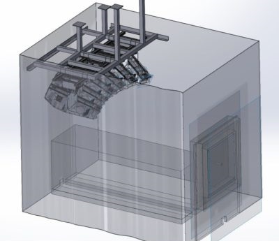
**The proposed suspended solar simulator system in the end-user facilities
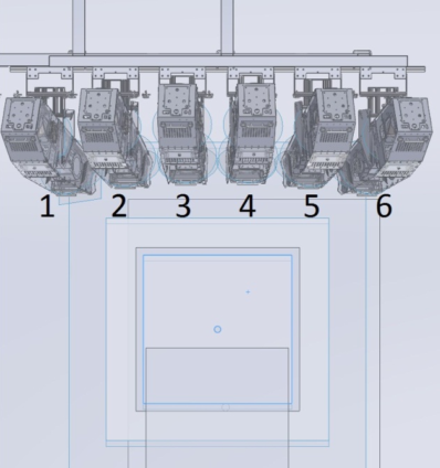
Mechanical drawing of the six suspended projector units pointing towards the target plane
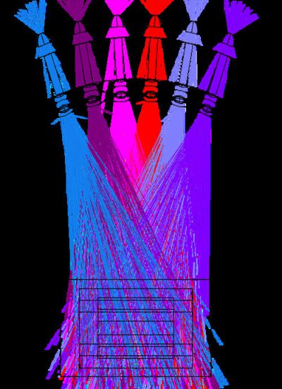
The light tracing model of the projector
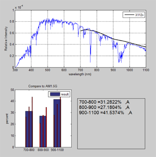
The spectral output of the solar simulator that generates infrared light is superimposed on the AM1.5G solar spectrum.
The time stability is classified as ASTM A grade. Its design has been improved to reduce the noise levels generated by the previous system. The system also includes a feedback system with a solar cell calibrated by science and technology to control and monitor the intensity changes within the light source.
Installation and support services
We successfully met all the requirements of the solar simulator. The final acceptance test was conducted at the end-user’s factory and was approved. The system was successfully installed by our support engineering team. The end-user was impressed by the design and operation of the system.
Recently, we received a third order for a similar solar simulator system from the same client.
。
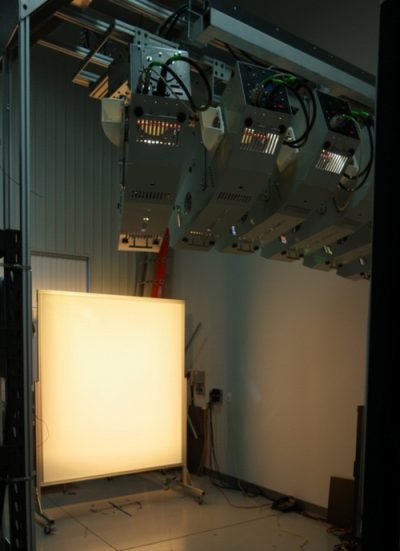
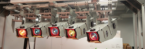
**The final product consists of six QTH projection units, which can illuminate a target area of 1.5m x 1.5m.
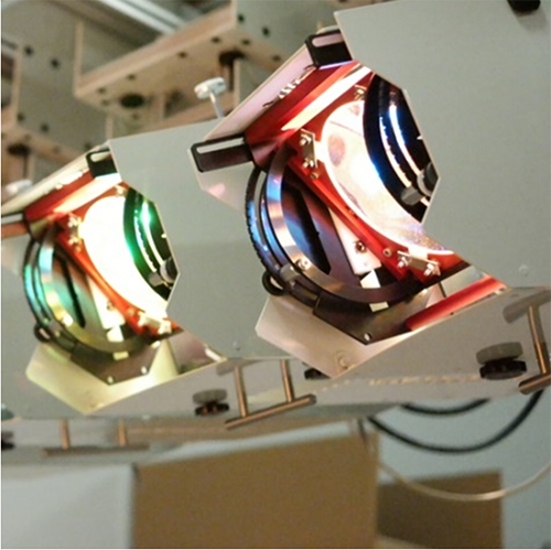
Six projector unit components are installed on a suspended rack for lighting purposes.